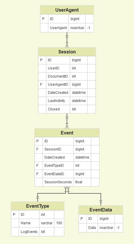
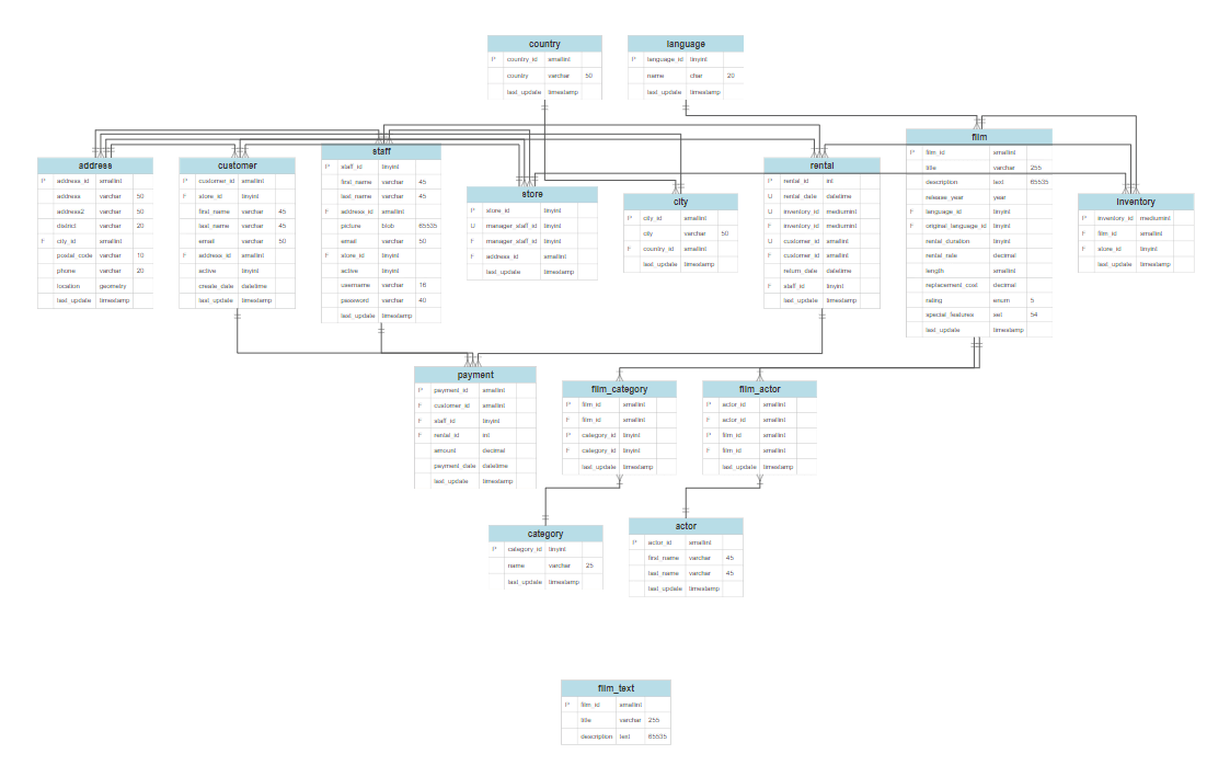
SmartDraw is the Best Way to Make a Diagram Online You Need to Update Your Browser SmartDraw is a full drawing application that runs inside of a modern, standards compliant browser. It looks like you're using an older browser that is not compatible with SmartDraw. Before SmartDraw can generate your database diagram, you'll have to export your data from your database. Below you'll find some scripts you can use for some common database types to get the data you'll need. Learn more about how to generate an ER diagram automatically using your exported data. For Microsoft SQL Server.
Made with
The main tool of domain modeling at the stage of conceptual design is the Entity-relationship model, also called ER-model. Modeling domain data structures is based on the usage of graphical tools - ER-diagrams (Entity-Relationship diagrams). Simply put, it is a visual representation of relationships between entities.
Erd Diagram Examples Pdf
The core concepts of ER Diagram are entity, attribute and relationship. An entity is an object of the real world that can exist independently. An entity has instances which differ in attribute values and allow unambiguous identification. An attribute is a property of the essence. For example, the entity named Book is characterized by attributes such as author, title, price, publishing house, edition, number of pages. Specific books are instances of the book entity. These instances vary in the values of these attributes and are uniquely identified by the attribute 'name'. Attribute that uniquely identifies the instance of the entity is called the primary key. It may also be a composite key, which is a combination of several attributes.
A very important feature of the entity-relationship model is that it can be represented as a graphical diagram. This greatly facilitates the subject area analysis. There are several notations used to represent entity-relationship elements, like Crow’s foot notation, or Chen notation, and each has its pros and cons.
Example 1. ER Diagram
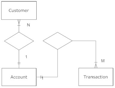
The entity on the ER-diagram is represented in the form of a rectangle, which indicates its name. Relationship is the interaction between entities, which is characterized by degree which counts how many entities are involved in the relation. The relationship between the two entities is called binary, and the relationship between more than two entities is ternary. Attributes, entities and relationships are connected by straight lines. Relation is shown in the form of a diamond. When creating a diagram, you can follow a few obvious steps. First, you need to identify entities and relationships among them. The following step is to identify the semantic information in the sets of relations (for example, whether a certain set of connections is a 1:n relation). Then you should define relationships cardinalities and determine attributes and their values sets. The final step is to organize the data in the form of entity-relationship connections.
As an example, let’s imagine a database designed for storing information about some bank activities. The bank has affiliates, which are controlled by managers. Customers of the bank have different types of accounts - current, term, demand, deposit, card account. Branches handle these accounts. The described domain will be called Bank. Let’s determine four entities: the Affiliate, the Manager, the Account, the Customer and some relations among them: the Manager controls the Affiliate; the Affiliate handles the Account; the Customer has the Account.
ConceptDraw DIAGRAM with Entity-Relationship Diagram (ERD) solution serving as ERD software allows you to visually create Entity Relationship diagrams (ERDs) for various database systems, it supports ODBC-compatible databases (Oracle, MS SQL, InterBase, MySQL, MS Access, Firebird and others). The built-in scripting language allows to connect to ODBC-compatible databases and automatically generate the structure of a database (reverse engineering of the database structure).
Example 2. ConceptDraw DIAGRAM ER Diagram Tool
ConceptDraw ER Diagram Tool works across any platform, meaning you never have to worry about compatibility again. ConceptDraw DIAGRAM allows you to make Entity-Relationship Diagram (ERD) on PC or macOS operating systems.
When creating an ERD our ERD software considers individual database options such as referential integrity, constraints, domains, triggers, stored procedures, functions, packages, views, sequences, synonyms etc.
Discovery usb microscope vms 001. Veho VMS-001 Usb Microscope Driver? Is commonly caused by incorrectly configured system settings or irregular entries in the Windows registry. This error can be fixed with special software that repairs the registry and tunes up system settings to restore stability. The Veho VMS-001 Discovery USB desktop microscope has a 1.3 Mega Pixel CMOS lens that enables upto x200 magnification.The software bundled with the VMS-001 allows;- Snapshot photo capture- Video Capture- Point to point measurement- Save and Share JPG images or AVI movies- Supports Win2k/XP/Vista/Win7/Mac The VMS-001 has a multiude of home and office uses including;Science. VMS-001 This handy USB desktop microscope 20x-200x, 1.3 Mega Pixels magnification - has a multitude of home and office uses; science education, laboratory research, computer parts examination, printing inspection, presentation tool, medical analysis, reading aid.

ConceptDraw DIAGRAM is a very easy-to-use and intuitive database design tool and ER Diagram tool which can save you hundreds hours of work. Entity-Relationship Diagram (ERD) solution contains 2 libraries with 45 predesigned vector graphic elements, collection of professional ERD samples, examples and templates.
ConceptDraw DIAGRAM is excellent choice of database designers for modeling, reverse and forward engineering of relational databases. It is not only an excellent tool for ER Diagram, but also the one that allows you to reverse engineer already existing database structures, create detailed HTML, PDF or PPT reports.
Example 3. ER Diagram (ERD)
The ER Diagram samples you see on this page were created in ConceptDraw DIAGRAM using the Entity-Relationship Diagram (ERD) Solution. They successfully demonstrate solution's capabilities and professional results you can achieve. An experienced user spent 10 minutes creating every of these samples.
Use the Entity-Relationship Diagram (ERD) Solution for ConceptDraw DIAGRAM software to create your own professional looking ER Diagrams quick, easy and effective, and then successfully use them in your scientific or education activity.
All source documents are vector graphic documents. They are available for reviewing, modifying, or converting to a variety of formats (PDF file, MS PowerPoint, MS Visio, and many other graphic formats) from the ConceptDraw STORE. The Entity-Relationship Diagram (ERD) Solution is available for all ConceptDraw DIAGRAM or later users.
NINE RELATED HOW TO's:
Pyramid Diagram →
When thinking about the process of decision making, it's easy to imagine it as a pyramid. We will look at a three level pyramid model as an example. Operational decisions are first that come to mind, and it's the first level. Tactical and strategic decisions are the second and the third levels. Pyramid (triangle) diagrams are used to show some hierarchical data. Because to the pyramid form of diagram, each diagram slice has a different width. The width of each segment depends on its hierarchical level. The current image illustrates the model of information system types. Most graphically the model can be represented as a three level pyramid. The first level shows a system of transaction processing It is concentrated on operational tasks. The second level is devoted to tactical solutions of the information system management. And at least, the third level addresses strategy and represents the executive information system. This three level pyramid sample is supplied with the ConceptDraw Pyramid Diagrams solution from Marketing area of ConceptDraw Solution Park.
Flowchart Definition →
Acquaintance with flowcharting starts from getting into basic terms. First of all, flowchart definition is quite clear – a flowchart is a graphical representation of a process or an algorithm made of special symbols. Secondly, flowcharting is an irreplaceable tool for IT specialists, project managers, and anyone who wants a clear understanding of any imaginable process.Online Collaboration via Skype →
Collaborating with co-workers is very important, not only in order to get things done effectively, but also to keep in touch with the outside world. Great way for business collaboration is Skype.How to Draw Pictorial Chart. How to Use Infograms →
How to draw pictorial chart quick, easy and effective? ConceptDraw DIAGRAM offers the unique Pictorial Infographics Solution that will help you! Pictorial Infographics solution contains large number of libraries with variety of predesigned vector pictograms that allows you design infographics in minutes. There are available 10 libraries with 197 vector pictograms. How to Use Infograms *'>Accounting Flowchart Symbols →
How To Draw Erd Diagram
It doesn’t matter what kind of business you have, a bar or a gym, there are common concepts for any of them. One of those concepts is accounting, and to facilitate the work with the figures, you can use accounting flowchart symbols and create a clear and representative scheme. You can create flowchart for auditing, tax accounting and even for planning your own budget. A graphical tool for displaying successive processes is flowchart. This method is mostly suited to represent an accounting process. The sequence of steps in the accounting process usually consists of standard accounting procedures, that can be depicted by using a minimal number of symbols, applied for the basic flowcharting. The advanced opportunity to create professional Accounting Flow charts is provided by ConceptDraw Accounting Flowcharts solution. It includes contains a library of accounting flowchart symbols used when drawing the accounting process flow.
Simple Drawing Applications for Mac →
ConceptDraw gives the ability to draw simple diagrams like flowcharts, block diagrams, bar charts, histograms, pie charts, divided bar diagrams, line graphs, area charts, scatter plots, circular arrows diagrams, Venn diagrams, bubble diagrams, concept maps, and others.Free Erd Software
Influence Diagram Software →
 Influence diagram (ID) is a graphical and mathematical representation of the decision. Influence diagrams are widely used in the decision analysis and in the game theory. They are the alternative to the decision tree. The influence diagram gives to analyst the high-level conceptual view that it can use to build the detailed quantitative model. This sample shows the Influence diagram. It is a directed acyclic graph with three types of nodes: Decision node is drawn as a rectangle, Uncertainty node is drawn as an oval, Value node is drawn as an octagon. The nodes are connected with arcs.
Best Program to Make Flow Chart Diagrams →
ConceptDraw the best business process modeling tool to make flow chart diagrams. Start creating your own flowchart with ConceptDraw DIAGRAM and accomplish great results in the moment. This is the best program to make flow chart diagrams that gives users the ability to simply draw any type of flowchart. The fast creating visualization for the structural data with the vector stencils from object libraries by using RapidDraw technology makes ConceptDraw DIAGRAM the first program in drawing flow data.Smartdraw Entity Relationship Diagram
